VEHICLE DESIGN • FEA • MANUFACTURING
Baja SAE Front Upright
Designed and optimized a lightweight front upright for the Johns Hopkins Baja SAE vehicle using SolidWorks, ANSYS, engineering drawings, GD&T, and design-for-manufacturing principles.
Drag to rotate • Scroll to zoom
OVERVIEW
Designing a critical suspension component
The front upright connects the wheel hub, control arms, and steering linkage. Its geometry influences suspension movement, steering behavior, vehicle handling, and unsprung mass.
I designed the assembly around the vehicle’s suspension hard points while accounting for bearing placement, fastener access, component clearances, steering geometry, structural loads, and manufacturing limitations.
CAD AND DESIGN
Developing the upright geometry
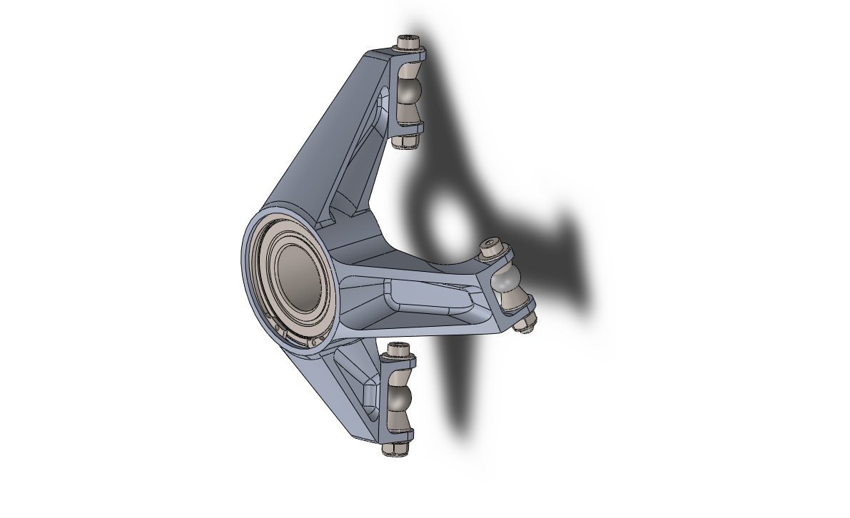
The upright was modeled in SolidWorks and integrated into the complete front suspension assembly. This allowed me to evaluate component clearances, suspension motion, bearing locations, and steering-arm placement.
The geometry was refined to remove unnecessary material while maintaining the stiffness needed to withstand off-road suspension and steering loads.
FINITE ELEMENT ANALYSIS
Evaluating stress and deformation
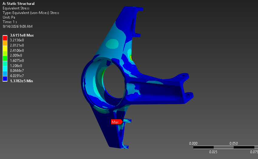
I used ANSYS to examine stress concentrations, deformation, and load paths under representative suspension and steering loads.
The simulation results helped identify areas that required reinforcement and regions where material could be removed. The design was iterated to balance mass, stiffness, manufacturability, and structural reliability.

MANUFACTURING
Preparing the design for machining
I created a detailed engineering drawing containing the dimensions, tolerances, datums, and GD&T needed to manufacture and inspect the component.
Tool access, fixturing, machining operations, and inspection requirements were considered throughout the design process to ensure the upright could be manufactured accurately.
PROJECT GALLERY
Design and manufacturing process


